Maximum voltage drop for fire alarm system
When Disaster Strikes Are You Prepared. A fire alarm manufacturer specifies a maximum allowable loop resistance of 50 1.

Understanding Fire Alarm Systems Iaei Magazine
The amount of that drop varies with every panel from about 5 volts to 25 volts.
. A zone is a defined area in a building in which related functional items work together. A fire alarm system component with discrete. As previously referenced the fire alarm system is required to perform at 85 of the name plate rated voltage.
By at least one-third the maximum diagonal of the notification or signaling zones that the pathways are passing through and the pathway is Class X or N. The 204 volts is the real-life worst-case scenario of what is needed to keep the fire alarm system working at the end of a 24 hour power blackout. Voltage drop calculations are required by the fire code.
Subtract the maximum voltage drop calculated in e above. This is the most conservative approach no matter what the input. The assumed voltage has to be that low because even if the power to the building has been out for 24 hours the fire alarm system still has to detect fire and warn people.
Drawings and calculators to help you effectively plan and prepare for your next fire safety system installation. Battery sharing calculations where applicable. So the maximum voltage drop permitted for this circuit is 44V.
Sample Fire Alarm System CalculationsDOC Page 7 05 October 2000 rpsa FIRE PROTECTION ENGINEERS. 522014 Fire Alarm FAQs Question Answer Q. NFPA 72-2016 2431341.
How many zonecircuit fire alarm panel do I need. Fire alarm panel and power supply battery calculations. This would be the minimum acceptable voltage at the end-of-line notification device.
Metrics for this calculation are. Automatic Fire Alarm Association Voltage Drop. Voltage drop is critical to the proper operation of devices attached to a fire alarm system.
The size of a fire alarm panel is determined by a number of factors including the size of the building the number of devices and the jobs requirements. Of safety would require that the voltage not drop below 09 x 22 198 20 VDC. Voltage drop calculations are prepared for the notification appliance circuits NAC as part of the fire alarm system design.
All fire alarm control panels and power supplies which are included have an internal voltage drop. Using a voltmeter measure the actual voltage being applied to the circuit at the control panel. These calculations assure that the devices on the system are supplied with electrical power within the operating voltage range.
Heres a good post on the subject matter. In practice youll have to know the maximum allowable current per in-panel NAC as well as the current drawn by each NAC device in. This requirement has been in the standards for some time.
If the transformer used to power the fire alarm devices is a 24 VDC transformer the starting voltage for the voltage drop calcs is 24VDC x 85 or 204 VDC. Jan 21 2012. Nowhere is this as true as with notification appliance circuits NACs that connect to a fire alarm control panel.
These calculations are a requirement of the submitted Fire Alarm Shop Drawings outlined in Section 90712 2018 Phoenix Fire Code. Ad Learn More About Our Fire Notification Systems Solutions. Activate the fire alarm system to cause the notification appliance circuit to operate.
The circuit in. Maximum voltage drop of 44V as. Up to 15 cash back Battery voltage drop and dB line loss calculations in one location.
The drop between 204V and 16V is 44V. The voltage at the NAC output terminals is always less than 204 volts at cut-off. Sample Fire Alarm System Calculations by Robert Schifiliti former NFPA 72 Member that does a good job of explaining the subject.
Some key features include. The article walks you though NFPA 72 albeit pre 2000 edition and explains that 204 volts is based on 85 of the power supplies Name Plate Rated Voltage and the need to.
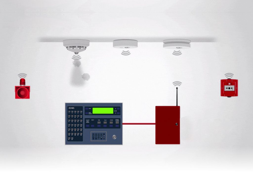
The Benefits And Challenges Of Wireless Fire Alarm Systems Worlds Only Media House Publishing 4 Monthly Magazines In The Field Of Fire Safety Security Disaster Managementworlds Only Media House Publishing
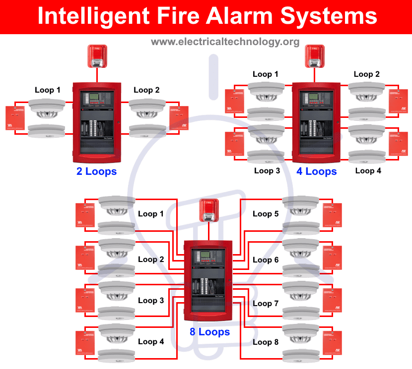
Types Of Fire Alarm Systems And Their Wiring Diagrams
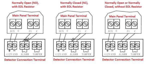
What Is End Of Line Resistor For Fire Alarm System Basics Guide Key Security

Fire Alarm Voltage Drop Calculation For Notification Appliance Firealarm Allaboutfireprotection Youtube

Voltage Drop For Fire Alarm Systems Fire Alarms Online

Voltage Drop For Fire Alarm Systems Fire Alarms Online

How To Do Fire Alarm Voltage Drop Calculations For System Sensor Spectralert Horn Strobes Hd Youtube

Voltage Drop For Fire Alarm Systems Fire Alarms Online
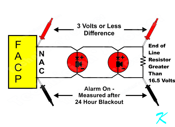
What Voltage Should Be At The Eol Of A Nac
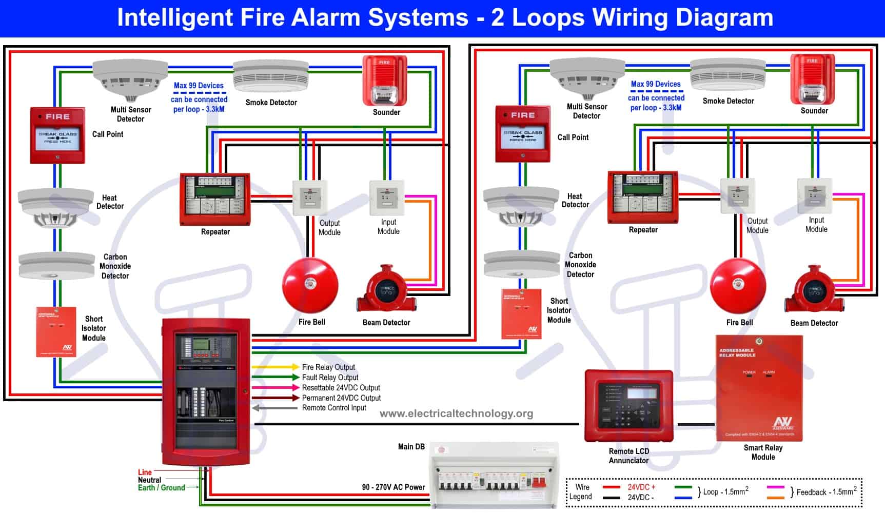
Types Of Fire Alarm Systems And Their Wiring Diagrams
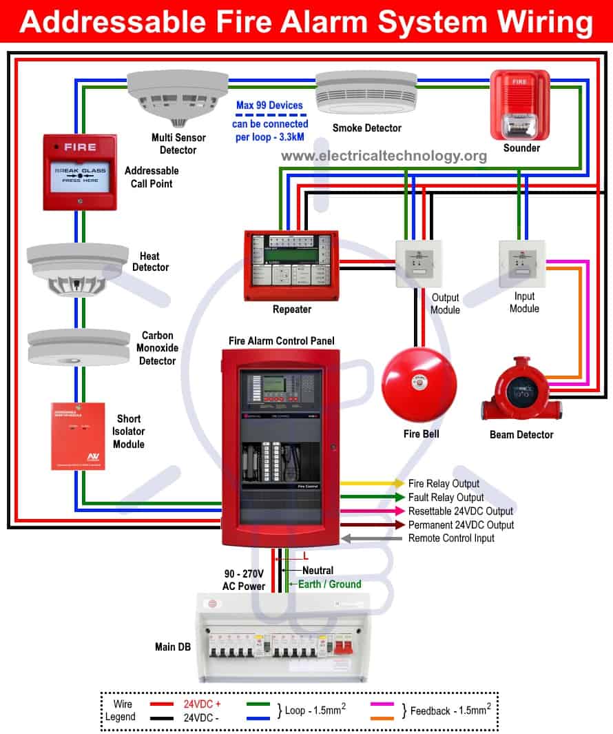
Types Of Fire Alarm Systems And Their Wiring Diagrams

Guide To Fire Alarm Basics Power Supplies Nfpa Nfpa
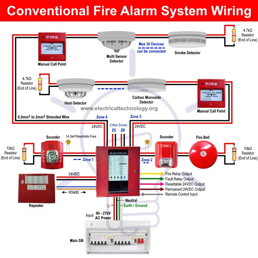
Types Of Fire Alarm Systems And Their Wiring Diagrams

Kidde I12040 Ac Hardwired Interconnect Smoke Alarm With Hush

Guide To Fire Alarm Basics Power Supplies Nfpa Nfpa
2

Calculation Crunching Fire Alarm Math You Should Know Electrical Contractor Magazine